drmax
New User
Feb 26, 2009, 4:00 PM
Post #18 of 25
(4243 views)
Shortcut
|
It is the same, here is the c/p from the service manual that you have downloaded....
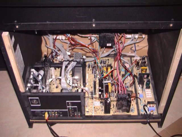
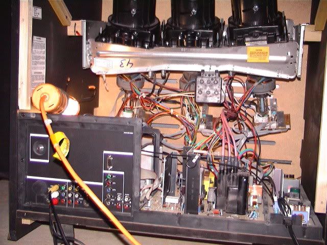
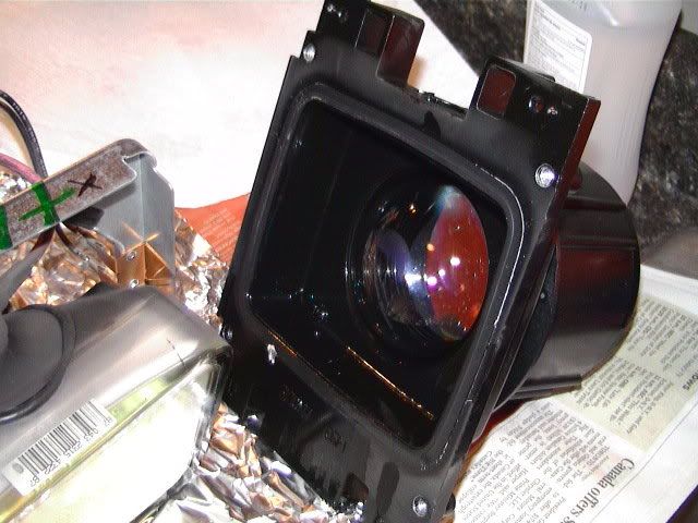
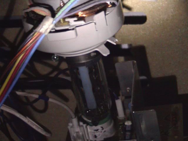
(it asks to work from the back, see steps directly below) Disassembly Procedures A. Removal of a single CRT/Lens Assembly from the light rack 1a) Remove AC power from the PTV. 2a) Remove the upper and lower back covers (1/4" screws). 3a) Remove the barrier board and the shield cover from around the lens assemblies (1/4" screws). 4a) Carefully remove the CRT Socket Board from the CRT of the CRT/optical assembly being serviced. 5a) Remove the yoke and convergence plugs, of the CRT/optical assembly being serviced, from the Large Signal Module. 6a) Remove the high voltage anode lead from the HV splitter block on the Large Signal Module of the CRT/optical assembly being serviced. Remove ground lug connectors from the coupler frame. 7a) Remove the four 1/4" screws that secure the CRT/lens assembly to the light rack. These four screws are located in each corner, on the top of the coupler assembly. Caution: Do not remove the bolts with pressure springs or the inverted Torx screws of the CRT/lens assembly. The removal of these components could result in fluid spillage into the PTV cabinet. 8a) Carefully remove the CRT/lens assembly from the PTV cabinet. Servicing the CRT/Optical Assembly Caution: Do not attempt any repairs on the CRT/optical block assembly without first removing the CRT coupling fluid. Removal of the delta output lens will result in spillage of the coupling fluid. Caution: Coupling fluid is a poisonous solution containing a high concentration of ethylene glycol. Do not leave exposed fluid unattended. Prevent children or pets from coming into contact with the fluid. Clean up spills immediately. B. Removing the PTV Coupling Fluid All repairs made to the CRT/optical block assembly require the removal of the coupling fluid. The following procedure describes how to remove the PTV coupling fluid. 1b) Lay the CRT assembly on its side with the plug pointing up. 2b) Remove the plug (X8). 3b) Remove some of the fluid from the coupler to prevent spillage when the CRT is removed. An empty coupling fluid bottle with a cone top is recommended to lower the fluid level within the coupler. Squeeze and hold the bottle and insert the tip of the cap into the drain hole of the coupler. Loosen the grip on the bottle, allowing the fluid to be pulled up into the bottle. Save the fluid. 4b) Reinstall the plug (X8). 5b) Stand the CRT assembly up with the neck of the CRT pointing up. 6b) With an awl or marking pen, outline the edges of the CRT onto the coupler. Note: The correct positioning of the CRT to the coupler is critical to the optimum performance of the optical system. 7b) Remove the four CRT mounting bolts (A) (with springs and spacers) and remove the mounting bracket (D). 8b) Remove the four CRT mounting ear screws. Note: The CRT mounting ear screws are not used on some assemblies. 9b) Gently remove any metal shavings from around the screw holes. Do not allow the metal shavings to get into the fluid. 10b) Note the position of the high voltage anode cap with respect to the coupler. 11b) Carefully remove the CRT from the coupler. Wipe any excess fluid from the faceplate of the CRT. Set the CRT aside. 12b) Use an empty coupling fluid bottle to extract the remainder of the fluid from the coupler. Note: Complete removal of the coupling fluid is not necessary when only replacing the CRT. 13b) Clean any remaining fluid from the coupler and the CRT gasket channel using absorbent tissue. Refer to "C�. Cleaning the Coupler, C-element Lens and CRT Faceplate procedure if the fluid is discolored or contaminated. 14b) Make all necessary repairs. C. Cleaning the Coupler, C-element Lens and CRT Faceplate 1c) Remove CRT coupling fluid as described in steps 1b through 13b. 2c) Using denatured alcohol on a cloth made of 100% cotton or a lens cleaning tissue, gently clean the Celement (fisheye) lens, coupler and the CRT faceplate. Thoroughly clean the coupler assembly, including the expansion chamber bladder, and allow to fully dry. Caution: Do not use soap or detergent type substances to clean the coupler and its related assemblies. Water can be used as an alternative to denatured alcohol, but the assemblies must be completely dry prior to reassembly of the coupler and the addition of the coupling fluid. A hair dryer may be used to dry the coupler and its assemblies prior to reassembly. If contaminated fluid is discovered, the coupler and its related assemblies must be completely disassembled and cleaned to prevent a reoccurrence. 3c) Replace the CRT and C-element lens gaskets. 4c) Reassemble the C-element lens and the output lens to the coupler. 5c) Refer to "Replacing the CRT Coupling Fluid" upon completion of necessary repairs and cleaning of the optical/coupler assemblies. D. Replacement of the CRT 1d) Remove CRT coupling fluid as described in steps 1b through 13b. 2d) Remove the plastic protective coating (if present) from the faceplate of the replacement CRT. 3d) Refer to "Replacing the CRT Coupling Fluid" to complete the CRT replacement. E. Repair or Replacement of the Optical/Coupler Assembly 1e) Remove CRT coupling fluid as described in steps 1b through 13b. 2e) Remove the four inverted-type Torx screws which secure the Delta output lens to the coupler. An inverted-type Torx socket can be purchased using part number 483539517303. 3e) Removal of the Delta output lens will allow access to the C-element lens, C-element gasket, coupler, and its assemblies. 4e) Refer to "Replacing the CRT Coupling Fluid" upon completion of necessary repairs to the optical/coupler assemblies. F. Replacing the PTV Coupling Fluid Note: Prior to replacing the CRT coupling fluid, ensure the expansion chamber bladder is fully collapsed. This can be easily inspected by viewing the bladder through the small hole on the expansion chamber assembly. If the rubber of the bladder is not easily visible through the small hole, then the bladder may be considered collapsed and fluid can be added. If the rubber of the expansion chamber bladder is visible at the hole of the expansion chamber, then replacement of the expansion chamber bladder is required. Note: The CRT coupling fluid is critical to the optical performance of the PTV. Use only part number 483531057233 (3 bottle kit) or 483531067004 (1 bottle) to ensure the optical integrity and performance reliability of the PTV when replacing the CRT coupling fluid. 1f) Reinstall the CRT gasket into the gasket channel of the coupler. Confirm the placement of the CRT, C-element lens, and vent plug gaskets. 2f) Place the CRT onto the coupler with the high voltage anode lead positioned as marked in step 10b of procedure B. 3f) Carefully position the CRT onto the coupler, using the outline defined in step 6b of procedure B as a reference. 4f) Start the CRT mounting ear screws but do not tighten them. 5f) Tighten the CRT mounting ear screws in a star pattern (like tightening lug nuts on the wheel of a car). Make sure the CRT does not shift position from the outline defined in step 6b. Caution: Do not over tighten the CRT ear screws. Note: The CRT mounting ear screws are not used on some assemblies. 6f) Install the CRT mounting bracket and start the four CRT mounting bracket bolts with springs. 7f) Tighten the bolts in a star pattern. 8f) Lay the CRT assembly on its side with the plug pointing up. 9f) Remove the plug. 10f) Using the PTV coupling fluid bottle with the cone top, refill the coupler with fluid through the drain access hole. Completely fill the coupler chamber so the fluid is level with the top of the coupler at the plug. Wipe any excess fluid from around the coupler. 11f) Reinstall the plug and check for any fluid leaks.
12f) Install the repaired CRT/optical block assembly into the PTV and perform any necessary adjustments
|


 ....
.... 
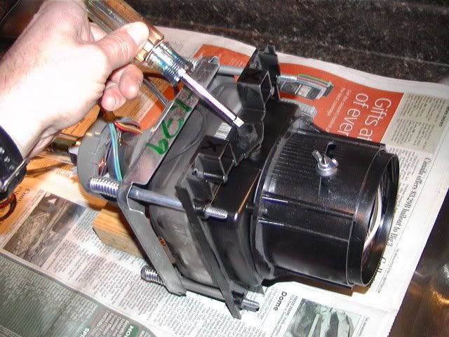
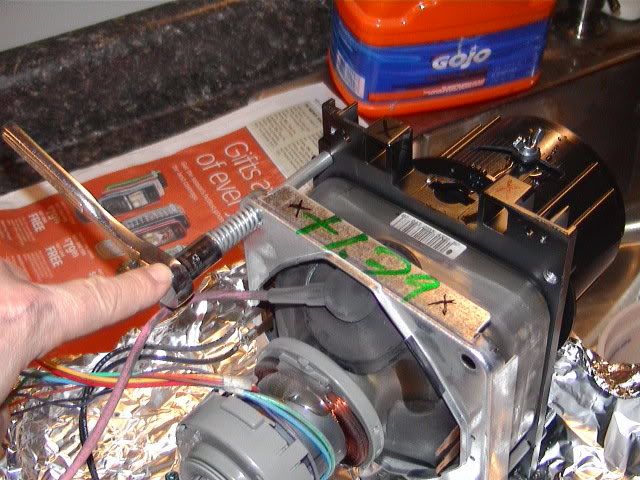
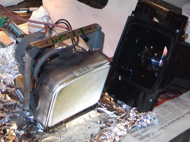
 ...OK ...Here we go...First I NEED to know EXACTLY how you changed the coolant...As close to step by step as you can inform me...Did you remove or disturb ANY of the items on the CRT's , ie , yokes , collars , etc...??? Did you remove the CRT's COMPLETELY from the lens assembly ?? Did you clean thoroughly the face of the CRT's with Windex or the equivilent & a SOFT rag ?? AND did you do the same to the inside of each lens where the coolant contacts ??..Did you do ANY convergence adjustments AFTER you changed the coolant ??<==ALL of this IS important for me to find out...

 Re: [drmax] Phillips 55PP9352 55...no green
[
Re: [drmax] Phillips 55PP9352 55...no green
[
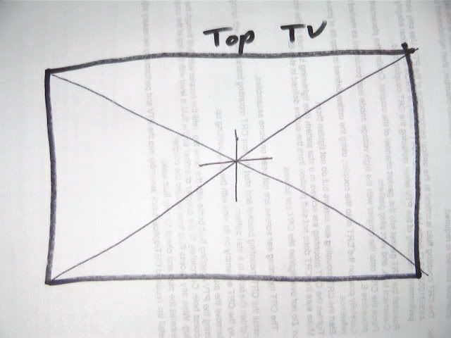
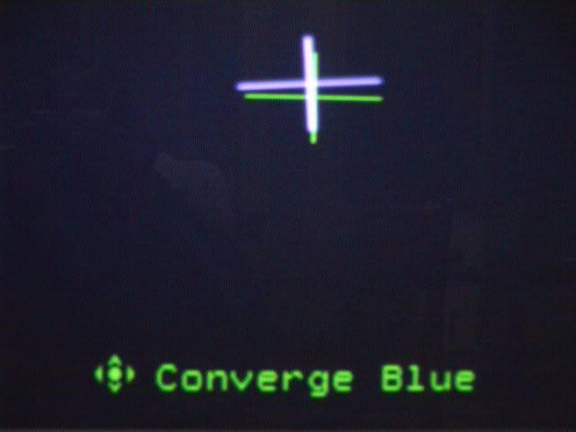
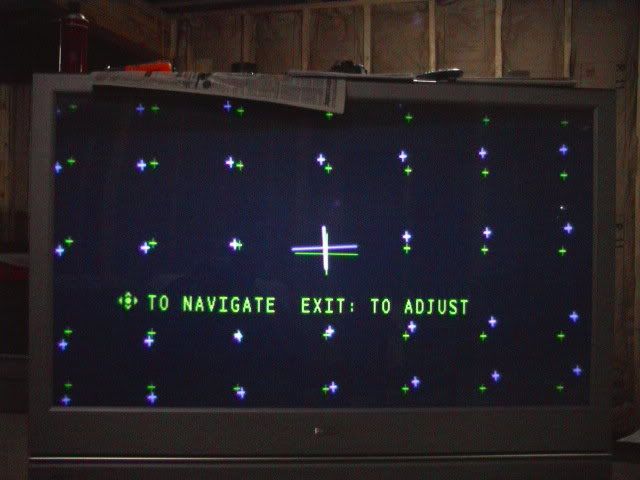
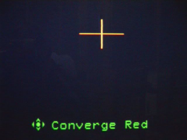
 ...) the "cross" is right where it should be...